

Multi-axis motion controller synchronises press operation
Gasbarre Products, Inc. of Dubois, PA, USA makes powder compacting presses in a variety of sizes, capable of exerting compaction forces from 1 to 750 tons. Most of the company’s customers are suppliers to the auto, lawn and garden, hand tool, and recreational vehicle industries. Gasbarre’s presses are used to form complex shapes from metallic and ceramic powder compounds, which are hardened through a high-temperature sintering process after forming.
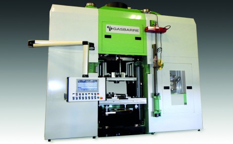
The size of a press is determined by the part face area and the compaction force of the material, but a common requirement is a need for multiple motion axes to accomplish the compression operation. For example, the following table contains an accounting of the axes involved in a new powder compacting press design (Figure 1) developed by Gasbarre:
Axis Function
Upper Ram The upper cylinder that creates the primary downward pressing force.
Upper #2 Second upper punch used for creating a hub or counter bore on the top of the part.
Die Table Contains the die for the outside diameter of the part. It will move up for die filling, down during the molding process, and down to eject the part.
Lower #1 Holds the first of three lower punches. The lower punches create different features on different levels on the bottom of the part. It will move up for filling, down during the molding process, and down to eject the part.
Lower #2 Same function as Lower #1
Lower #3 Same function as Lower #1
Core Rod An additional lower punch for creating a counter bore or thru hole from the bottom of the part.
Filler Shoe Controls a servo motor for this application which is used to deposit material into the die. An SSI rotary encoder is used to coordinate motion between the filler shoe and the die table.
Press operation
Figure 2 shows a manufactured part produced by the new press. Though it requires multi-axis compression to form, it is not as complex as parts which could be produced by the machine. During a compression cycle the axes will typically switch between geared, synchronised, and independent motion control at various times. This is all in an effort to consistently move the powder material into the machine and then transfer it within the die, so that when the part is molded, the density of each level stays within design specifications.
When decompressing the part, deflection compensation must be done on the various tool members because, depending upon the surface area of the punches, they will deflect differently. Without deflection compensation, as the tooling decompresses, the punches could spring back at varying rates, causing cracks in the part.
The next challenge is to extract the part from the die. The machine must have enough flexibility in speed, position control, and sequencing to eject the part from the die without creating any stress on the part which would result in cracks.
-
PPMA 2025
23 September, 2025, 9:30 - 25 September, 2025, 16:00
NEC, Birmingham UK -
Advanced Engineering Show 2025
29 October, 2025, 9:00 - 30 October, 2025, 16:00
NEC, Birmingham UK