Avoiding problems in electrohydraulic control systems design

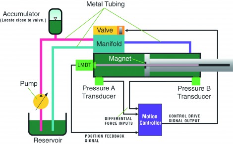
In the typical system where the required fluid flow changes over time, and short bursts of high flow are needed, an accumulator stores pressurised fluid. With the appropriately sized accumulator, the fluid pump doesn’t need to be sized to provide the maximum flow rate; rather it can be sized to meet the average flow needs.
To make the system easiest to control by an electrohydraulic motion controller, the accumulator should be large enough to prevent the pressure from changing by more than 10% during the system’s operating cycle. To minimise pressure losses during the cycle, the accumulator should be located close to the valve, not close to the pump.
What valves to use and which to avoid
Proportional servovalves should be used for precise control of the fluid flow. These valves provide a low-latency, linear response to control inputs from the motion controller, enabling smooth changes in fluid flow. Two-position directional valves cause shock and vibration and make precise cylinder control virtually impossible. Furthermore, valves with overlapped spools also exhibit control problems. Another problematic valve is a counterbalance valve, which operates autonomously to oppose the control inputs of a motion controller, making precise control difficult.
For maximum system responsiveness, valve sizing must not only take into account the required flow, but also the pressure drop across the valve. This ensures that enough pressure remains to accelerate and move the system. For a system with low mass and low friction, it may be sufficient to calculate the required flow, then add another 10 to 20%. For systems moving medium to large masses or experiencing high friction, more calculations must be made. If the valve is sized too large compared to the size of the cylinder, only a small part of the control range will be used and control of the valve will be coarse.
Valve placement can be critical for control, especially for systems that need to acceleration quickly or that exhibit significant stiction. Valves should be placed as close as possible to the cylinders to minimise the effects of fluid compressibility in the lines. Where possible, using metal tubing instead of flexible hose will minimize controllability problems due to expansion in the lines.
Which transducers are best
Hydraulic systems commonly employ linear displacement transducers to measure cylinder position, and pressure transducers or load cells to measure force. It is critical that devices be chosen that have high response – significantly faster than the control loop time of the motion controller – and fine granularity of measurement. A common mistake is to choose a transducer that provides the same resolution as the required motion tolerance. Instead, the transducer resolution should preferably be ten times greater or more. For systems with poor controllability, even higher resolution may be required to take advantage of compensating control algorithms.
-
PPMA 2025
23 September, 2025, 9:30 - 25 September, 2025, 16:00
NEC, Birmingham UK -
Advanced Engineering Show 2025
29 October, 2025, 9:00 - 30 October, 2025, 16:00
NEC, Birmingham UK


