

Avoiding problems in electrohydraulic control systems design
By Jacob Paso, Delta Computer Systems Inc.
Closed-loop control gives machines great precision to apply force or lift heavy objects or follow very precise motion profiles. Set up incorrectly, however, an electrohydraulic linear motion system can be unstable and cause damage to products or be dangerous to people.
The key to unlocking the benefits of electrohydraulic control is understanding system requirements, selecting the proper system components, sizing them appropriately, and correctly programming and tuning the motion controller for optimal performance.
Selecting/sizing cylinders
Building a precisely controllable motion system is all about understanding the concepts of force and natural frequency. For a typical hydraulic motion system, the acceleration and velocity are limited by the available force, not the flow. In addition, the natural frequency of a system determines the maximum acceleration rate that it can achieve under control.
Where mistakes are often made is in cylinder diameter. Cylinder choice is crucial since both the force it can apply, and the natural frequency of the system are functions of the cylinder diameter. A common error is to use small diameter cylinders that are capable of moving very quickly under light loads. Unfortunately, under higher loads, the piston in a narrow cylinder provides too little surface area for hydraulic oil flow to push on to produce the required force. A small diameter cylinder acts like a hydraulic spring, resulting in a low natural frequency, especially if the system has a large mass. This can cause oscillation if the motion profile requires quick acceleration, or if the system exhibits stiction (static friction exceeds dynamic friction).
The natural frequency of a system is related to its stiffness. Because fluid is compressible, a fluid power system with a large bore is much stiffer than a system using a long, narrow cylinder. Hence, systems with larger bore diameters will not compress as much when accelerating and are capable of quicker controlled acceleration and deceleration. As a general rule, in order to be precisely controllable by a standard PID algorithm, the natural frequency of a cylinder acting on a particular load mass should be three to four times greater than the frequency at which the system is commanded to move.
Choosing pumps and accumulators
After the cylinders are chosen, the next step is to size the hydraulic pump correctly to provide fluid flow in order to support the required cylinder speed. If the pump is too large, fluid and energy may be wasted. If the flow is too small, the system won’t perform even with the correct cylinders. The optimal flow calculation is relatively simple: The required volume of oil flow matches the required change in internal volume of the cylinder over time. Because the flow is proportional to the square of the cylinder diameter, doubling cylinder diameter requires four times the flow.
In the typical system where the required fluid flow changes over time, and short bursts of high flow are needed, an accumulator stores pressurised fluid. With the appropriately sized accumulator, the fluid pump doesn’t need to be sized to provide the maximum flow rate; rather it can be sized to meet the average flow needs.
To make the system easiest to control by an electrohydraulic motion controller, the accumulator should be large enough to prevent the pressure from changing by more than 10% during the system’s operating cycle. To minimise pressure losses during the cycle, the accumulator should be located close to the valve, not close to the pump.
What valves to use and which to avoid
Proportional servovalves should be used for precise control of the fluid flow. These valves provide a low-latency, linear response to control inputs from the motion controller, enabling smooth changes in fluid flow. Two-position directional valves cause shock and vibration and make precise cylinder control virtually impossible. Furthermore, valves with overlapped spools also exhibit control problems. Another problematic valve is a counterbalance valve, which operates autonomously to oppose the control inputs of a motion controller, making precise control difficult.
For maximum system responsiveness, valve sizing must not only take into account the required flow, but also the pressure drop across the valve. This ensures that enough pressure remains to accelerate and move the system. For a system with low mass and low friction, it may be sufficient to calculate the required flow, then add another 10 to 20%. For systems moving medium to large masses or experiencing high friction, more calculations must be made. If the valve is sized too large compared to the size of the cylinder, only a small part of the control range will be used and control of the valve will be coarse.
Valve placement can be critical for control, especially for systems that need to acceleration quickly or that exhibit significant stiction. Valves should be placed as close as possible to the cylinders to minimise the effects of fluid compressibility in the lines. Where possible, using metal tubing instead of flexible hose will minimize controllability problems due to expansion in the lines.
Which transducers are best
Hydraulic systems commonly employ linear displacement transducers to measure cylinder position, and pressure transducers or load cells to measure force. It is critical that devices be chosen that have high response – significantly faster than the control loop time of the motion controller – and fine granularity of measurement. A common mistake is to choose a transducer that provides the same resolution as the required motion tolerance. Instead, the transducer resolution should preferably be ten times greater or more. For systems with poor controllability, even higher resolution may be required to take advantage of compensating control algorithms.
A big advantage to using linear magnetostrictive displacement transducers (LMDTs) is that they always know the cylinder’s position; no homing step is required at system initiation or reset. LMDTs have the additional advantage of providing non-contacting measurements, which means that there are no contacts to wear out and cause maintenance problems, and repeatability of measurements is high.
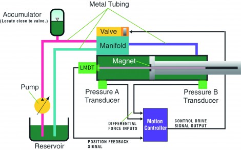
Figure 1 shows how the components of an electrohydraulically-controlled system are connected. In this system, force exerted by the cylinder can be measured by calculating the difference in reading between the outputs of pressure transducers mounted on either side of the piston.
System designers will benefit in terms of best system repeatability, highest productivity and longest machine useful life by selecting the highest quality components according to the guidelines above. This comes at a cost, however, and some designers are tempted to use less-than-optimal components to reduce system costs. Note that even the best motion controller may not be able to compensate for a poor system design or implementation.
Programming the motion controller
This being said, some electrohydraulic motion controllers, such as the RMC200 from Delta Computer Systems, Inc. (Figure 2), can compensate for some design problems. For example, Delta Computer Systems engineers recently analysed a customer system that was exhibiting the effects of static friction, sometimes called a stick-slip problem.
The application, a gang saw ‘wiggle box’ that needs to move in following the curve of a cut log, was vibrating when it should have been moving smoothly. The problem was diagnosed as being caused by the bores of two of the cylinders being too small, meaning that the system had a low natural frequency and was not as stiff as it should be. Hence, it wasn’t responding quickly enough to control signals from the motion controller.
The ‘D’ velocity term in the PID loop equation wasn’t producing enough drive to each valve. The Delta engineers solved the problem by increasing the gain of the acceleration component of the control loop algorithm (the ‘D Diff’ gain in Figure 3), which gave increased fluid flow to the cylinder to provide extra energy to the motion. In this case, the second derivative gain is applied to the error between the target and actual cylinder acceleration values, overcoming the effects of stick-slip and compensating for the too-small cylinders.
Another technique for improving the performance of lagging hydraulic motion systems is to use feed forwards, predictive terms that are incorporated in the closed-loop control algorithm (the ‘FF’ gains in Figure 3). Feed forwards for velocity and acceleration can ‘look forward’ and predict the required oil flow needed to achieve the desired velocity or acceleration, respectively. These terms anticipate where the system needs to be, and reduce the load on the P, I, & D gains to match the targets.
Because the effectiveness of a closed-loop control system depends on the system’s response to the error between the actual and target measurements of the system, it may take a long time for an actuator to start from a stopped state. This is because it may take a while for the P and I terms in the control algorithm to generate a strong enough output signal to cause the actuator to move.
If quick motion is necessary, a feedforward component can be added that anticipates the drive required to start the motion. A good design practice is to use feedforwards to produce the bulk of the motion drive signal, with the P, I and D terms doing fine-tuning of the motion in response to smaller error factors than would occur if the PID factors were used alone. Using the PID terms in this manner focuses that part of the algorithm to respond to environmental conditions such as temperature changes that can vary from production cycle to production cycle.
But what happens if fast-changing feedback levels cause the motion controller to change its outputs too quickly, a phenomenon that could be a result of noisy transducer connections. Figure 3 shows the inclusion of an output filter between the output of the control loop and the connection to the valve. In the case of Delta Computer Systems’ motion controllers, support for output filtering is provided as a standard programming function.
Good tools help with diagnosing and fixing problems
When selecting a motion controller, designers should look for a product that is supported with tools to simplify the development and tuning of motion systems, as well as diagnostic tools that can help isolate system problems. Delta Computer Systems’ Plot Manager, a feature of the company’s RMCTools support package, can be used to monitor how the actual motion differs from target motion during an operational cycle. It was by using the Plot Manager that the engineers identified a problem with tuning the motion of the gang saw wiggle box described above.
Another Delta tool is the Tuning Wizard, which can be used to automatically generate a set of control parameter gains that will reduce the error between the target and actual motion profile (see Figure 4). Further tweaking is sometimes necessary, but the Tuning Wizard will accelerate the tuning process. In the case of the wiggle box problem, the actuator tuned up easily after changing the tuning to acceleration control using the Delta’s Tuning Wizard. The tuning process took less than 10 minutes.
By choosing the correct system components, including the right motion controller and automated tools such as these, hydraulic system designers can avoid some difficult problems and gain the full potential of hydraulic power.
-
Farnborough International Airshow
22 - 26 July, 2024
Farnborough International Exhibition & Conference Centre