Avoiding problems in electrohydraulic control systems design

A big advantage to using linear magnetostrictive displacement transducers (LMDTs) is that they always know the cylinder’s position; no homing step is required at system initiation or reset. LMDTs have the additional advantage of providing non-contacting measurements, which means that there are no contacts to wear out and cause maintenance problems, and repeatability of measurements is high.
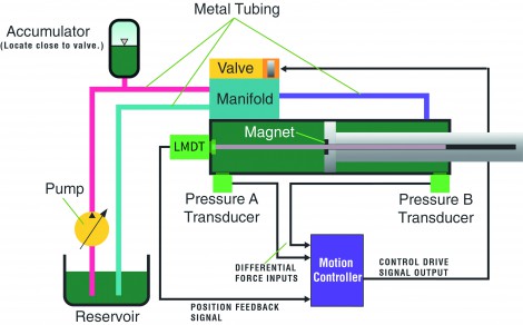
Figure 1 shows how the components of an electrohydraulically-controlled system are connected. In this system, force exerted by the cylinder can be measured by calculating the difference in reading between the outputs of pressure transducers mounted on either side of the piston.
System designers will benefit in terms of best system repeatability, highest productivity and longest machine useful life by selecting the highest quality components according to the guidelines above. This comes at a cost, however, and some designers are tempted to use less-than-optimal components to reduce system costs. Note that even the best motion controller may not be able to compensate for a poor system design or implementation.
Programming the motion controller
This being said, some electrohydraulic motion controllers, such as the RMC200 from Delta Computer Systems, Inc. (Figure 2), can compensate for some design problems. For example, Delta Computer Systems engineers recently analysed a customer system that was exhibiting the effects of static friction, sometimes called a stick-slip problem.
The application, a gang saw ‘wiggle box’ that needs to move in following the curve of a cut log, was vibrating when it should have been moving smoothly. The problem was diagnosed as being caused by the bores of two of the cylinders being too small, meaning that the system had a low natural frequency and was not as stiff as it should be. Hence, it wasn’t responding quickly enough to control signals from the motion controller.
The ‘D’ velocity term in the PID loop equation wasn’t producing enough drive to each valve. The Delta engineers solved the problem by increasing the gain of the acceleration component of the control loop algorithm (the ‘D Diff’ gain in Figure 3), which gave increased fluid flow to the cylinder to provide extra energy to the motion. In this case, the second derivative gain is applied to the error between the target and actual cylinder acceleration values, overcoming the effects of stick-slip and compensating for the too-small cylinders.
Another technique for improving the performance of lagging hydraulic motion systems is to use feed forwards, predictive terms that are incorporated in the closed-loop control algorithm (the ‘FF’ gains in Figure 3). Feed forwards for velocity and acceleration can ‘look forward’ and predict the required oil flow needed to achieve the desired velocity or acceleration, respectively. These terms anticipate where the system needs to be, and reduce the load on the P, I, & D gains to match the targets.
Because the effectiveness of a closed-loop control system depends on the system’s response to the error between the actual and target measurements of the system, it may take a long time for an actuator to start from a stopped state. This is because it may take a while for the P and I terms in the control algorithm to generate a strong enough output signal to cause the actuator to move.
-
PPMA 2025
23 September, 2025, 9:30 - 25 September, 2025, 16:00
NEC, Birmingham UK -
Advanced Engineering Show 2025
29 October, 2025, 9:00 - 30 October, 2025, 16:00
NEC, Birmingham UK


